

Views: 0 Author: Site Editor Publish Time: 2026-07-24 Origin: Site


Disrupted municipal water supplies, lost agricultural yields, and unexpected industrial downtime present critical financial stakes. Groundwater extraction is rarely simple. Operators face extreme engineering challenges when pumping fluids from deep underground aquifers. You must constantly navigate fluctuating dynamic heads. Abrasive fluid conditions quickly destroy inadequate pumping equipment. Dropping water tables further complicate system reliability and predictability. You need a robust solution built to handle these harsh realities over decades. A Deep Well Turbine Pump remains the industry standard for high-volume, high-head stability. It provides unmatched performance in demanding environments. Specifying the right system requires balancing precise hydraulic design and advanced metallurgy. Proper upfront engineering ensures long-term operational sustainability and minimizes lifecycle energy expenses. You will learn how to evaluate various system architectures, select appropriate construction materials, and implement specific design features to maximize your overall plant efficiency.
System Architecture: Selecting between line-shaft vertical turbine pumps and submersible turbine pumps hinges on well plumbness, depth, and maintenance access.
Efficiency Metrics: Overall Plant Efficiency (OPE) is dictated by precise bowl assembly staging, impeller type, and thrust management.
Material Longevity: Customizing metallurgy (e.g., stainless steel, specific bronzes) prevents rapid degradation from sand, silt, and corrosive groundwater.
Installation Reality: Strict well casing alignment and vibration analysis are non-negotiable for line-shaft designs to prevent premature bearing failure.
Many operations severely underestimate the hidden financial burdens of pump failure. When a deep well system fails, the financial impact extends far beyond simple replacement parts. Emergency pulling operations require heavy cranes, specialized rigging crews, and expedited logistics. Motor rewinding demands significant off-site downtime. Lost production time often eclipses the initial capital cost of the equipment itself. We see facilities lose thousands of dollars daily due to preventable breakdowns. A reactive maintenance approach guarantees budget overruns.
Improper pump selection accelerates hydraulic degradation rapidly. Cavitation destroys impellers when engineers fail to calculate the required net positive suction head (NPSH). Sandy conditions cause rapid wear on internal components, acting like sandpaper against rotating metal. As the regional water table drops, mismatched systems suffer diminishing flow rates. The pump ends up operating far outside its Best Efficiency Point (BEP), which dramatically increases mechanical stress and power consumption.
We define stable extraction through highly specific success criteria. A successful installation delivers a consistent flow rate across varying Total Dynamic Head (TDH) conditions. It requires predictable, well-spaced maintenance cycles rather than constant emergency interventions. It also demands high energy efficiency throughout its operational life, ensuring that electrical consumption remains stable even as groundwater levels naturally fluctuate.
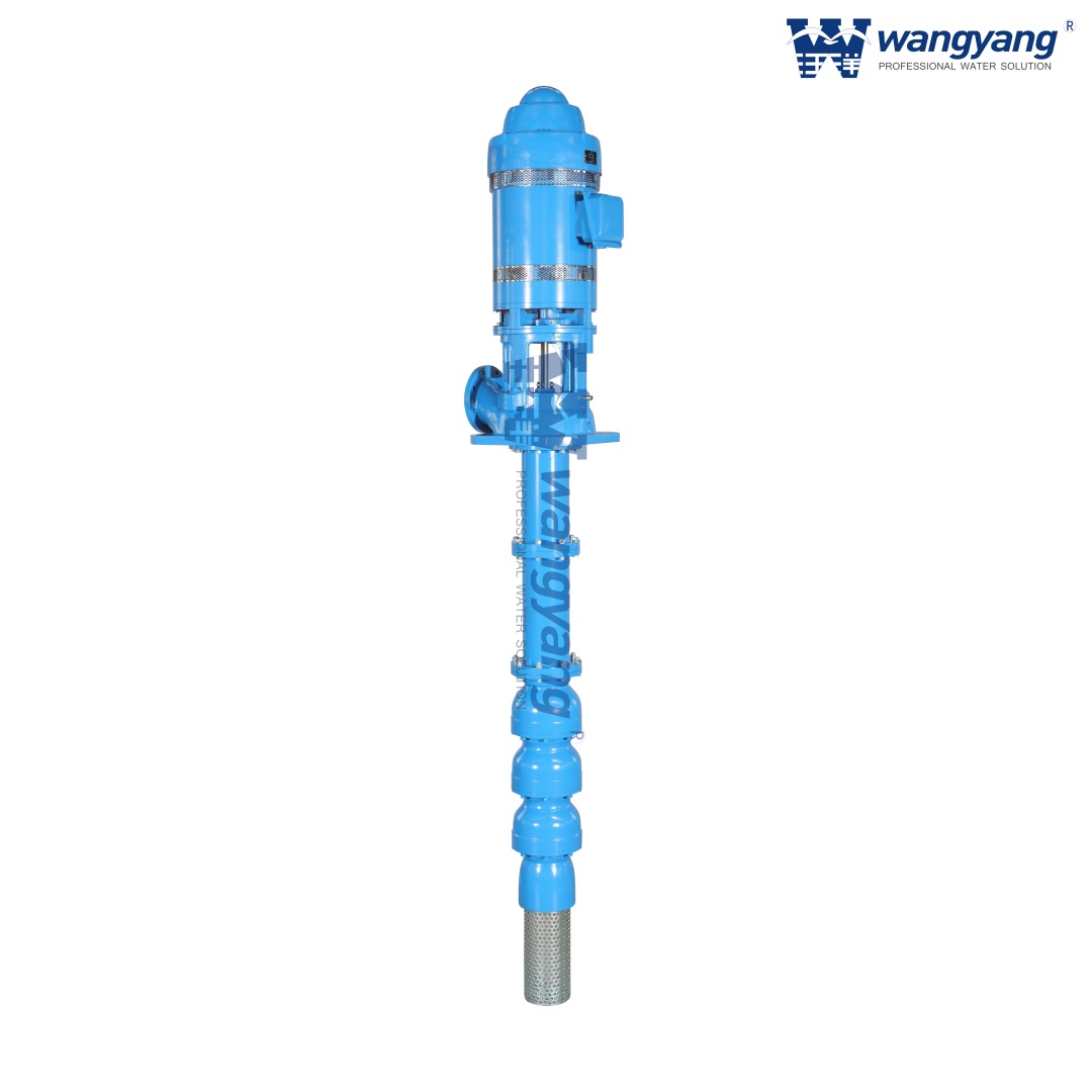
Selecting the right underlying architecture dictates your maintenance strategy and long-term system longevity. You must carefully choose between two primary configurations based on your site's physical constraints.
The mechanics of a vertical turbine pump (often called a line-shaft pump) involve a surface-mounted driver. A long vertical drive shaft connects the above-ground motor to the submerged hydraulic bowl assembly. You gain easier motor maintenance since the driver sits above ground, fully accessible to technicians. These systems generally offer exceptionally high overall efficiency. They easily adapt to different driver types, allowing you to use electric motors, right-angle gear drives, or diesel engines. However, this design requires strict well straightness. A crooked casing causes damaging shaft vibrations. Furthermore, extremely deep wells introduce shaft elongation issues, requiring precise surface adjustments to prevent impeller drag.
The mechanics of a submersible turbine pump place the entire unit underwater. The close-coupled electric motor directly attaches beneath the bowl assembly. They perfectly suit crooked or deviated wells where a rigid line-shaft would bind. You benefit from a much lower surface footprint, which is ideal for space-constrained sites. They operate almost silently, offering a massive advantage in urban or residential areas. On the downside, any motor failure requires pulling the entire heavy unit from the well. Furthermore, motor cooling strictly depends on continuous water flow past the exterior shell, making proper well casing sizing critical to prevent overheating.
Evaluation Criteria | Line-Shaft Design | Submersible Design |
|---|---|---|
Well Plumbness Requirements | Requires highly straight, plumb well casing | Highly tolerant of deviated or crooked wells |
Motor Maintenance Access | Excellent (surface mounted, easy visual inspection) | Poor (requires full unit extraction) |
Surface Footprint & Noise | Large footprint, moderate to high noise levels | Minimal footprint, virtually silent operation |
Driver Flexibility | Electric, diesel, or PTO driven | Strictly electrical submergible motors |
Achieving high Overall Plant Efficiency requires meticulous attention to the internal wet-end components. The choices you make here directly translate to your monthly utility bills and flow consistency.
Impeller selection sits at the heart of hydraulic performance. You generally choose between enclosed and semi-open designs. Enclosed impellers provide a higher initial efficiency. They are the ideal choice for clean water applications where suspended solids are minimal. The fluid remains contained within the impeller shrouds, reducing internal recirculation. Semi-open impellers offer better handling of suspended solids like sand or silt. They lack a front shroud, preventing debris from clogging the vanes. However, semi-open designs require precise, ongoing clearance adjustments at the surface to maintain their efficiency as parts gradually wear.
Multi-stage bowl assemblies give turbine pumps their unique versatility. By stacking multiple impeller and diffuser bowls vertically, adding stages linearly increases the head pressure. This modularity allows engineers to achieve massive lift capabilities without requiring a wider, more expensive well casing. Staging ensures the system maintains operation near the Best Efficiency Point (BEP) even when pushing water up hundreds of feet.
Thrust management protects the entire mechanical assembly. Deep well extraction generates massive downward axial forces. The weight of the long drive shaft, combined with the hydraulic down-thrust of the pumped water, creates immense load on the system. Heavy-duty thrust bearings, usually located in the surface motor of line-shaft models, absorb this force. Properly sizing these bearings prevents catastrophic motor failure and maintains exact impeller clearances.
Groundwater chemistry varies wildly from region to region. Failing to match your pump's metallurgy to the specific water profile guarantees rapid degradation.
Customizing metallurgy for corrosive and abrasive environments extends equipment life by decades. Standard cast iron bowls and bronze impellers work well in benign, neutral pH water. However, high-chloride water requires upgrades to 316 stainless steel or even specialized duplex alloys to prevent pitting and galvanic corrosion. Abrasive sandy water demands hardened materials. Engineers often implement sacrificial wear rings and specialized elastomeric bearing materials. These components are designed to sacrifice themselves gracefully, absorbing the wear to protect the much more expensive main shaft and impellers.
Lubrication systems must balance mechanical protection with environmental compliance. Open line-shaft systems rely on water lubrication. They use the pumped groundwater itself to lubricate the rubber shaft bearings. This method is strictly required for municipal drinking water compliance to prevent contamination. Enclosed line-shaft systems utilize oil lubrication. An outer tube protects the rotating shaft and bearings from abrasive sand, feeding oil down the line. While this protects bearings in highly sandy agricultural wells, it poses environmental contamination risks. Operators must use approved food-grade lubricants where regulated by local environmental authorities.
Even the most perfectly engineered pump will fail quickly if installed poorly. Field installation introduces variables that require strict quality control protocols.
Well plumbness and alignment represent critical engineering realities. A crooked well casing forces a rigid line-shaft to bend as it rotates. This causes severe harmonic vibration. It leads to rapid, catastrophic bearing destruction and eventual shaft failure. Before lowering any rigid equipment, operators must conduct a rigorous plumbness and alignment survey of the wellbore.
Critical speed and vibration analysis prevent self-destruction. During the design phase, manufacturers must perform torsional and lateral vibration analyses. Rotating equipment possesses natural resonant frequencies. If the pump's operating speed matches these frequencies, the resulting vibrations will quickly tear the equipment apart. Analyzing these factors ensures the unit operates smoothly across its entire variable speed range.
A strict pre-commissioning checklist mitigates startup disasters. Do not skip these mandatory steps:
Proper impeller lift adjustment: Technicians must adjust the surface top-nut to lift the shaft, ensuring impellers do not scrape the bowl castings.
Motor rotation check: Verify electrical phase alignment before coupling the motor to the shaft; reverse rotation can unthread the shafting instantly.
Baseline vibration readings: Capture initial vibration data to establish a healthy baseline for future predictive maintenance comparisons.
Submergence verification: Confirm the static and dynamic water levels satisfy the minimum required submergence to prevent vortexing.
Purchasing large-scale extraction equipment demands precise communication between site engineers and pump manufacturers. Ambiguous requests lead to underperforming systems.
Your RFP/RFQ data requirements must be exhaustive. Engineers must provide manufacturers with exact site data. You must include the well inner diameter, which dictates the maximum bowl size. Supply the static water level and the anticipated pumping water level (drawdown). Clearly state the target gallons per minute (GPM) and Total Dynamic Head (TDH). Crucially, include a comprehensive water chemistry report detailing pH, chlorides, and suspended solids. This report drives the metallurgical decisions.
Evaluating manufacturers requires looking far beyond the initial spec sheet. Assess the vendor's certified factory performance testing capabilities. Do they run full-scale tests to guarantee hydraulic performance before shipping? Investigate their local service network. You need a partner capable of executing emergency pulling and repairing operations quickly. Verify the long-term availability of replacement bowl assemblies and wear parts to ensure future serviceability.
For your next steps, request detailed pump curves from your shortlisted vendors. Analyze where your operating conditions fall on these curves. Calculate lifecycle energy costs based on motor efficiency and expected hydraulic degradation over time. Make your procurement decision based on long-term sustainability rather than just the lowest initial purchase price.
Securing a reliable deep well pumping system is a multi-decade investment. It requires exact alignment between your well's physical conditions, the pump's hydraulic design, and applied material science. You cannot cut corners on site data collection or material specification without sacrificing reliability. Balancing impeller types, staging, and lubrication methods ensures your system handles both fluctuating water levels and abrasive contaminants effectively.
Upfront engineering diligence drastically reduces your long-term operational expenses. Executing thorough water chemistry tests, verifying well plumbness, and insisting on factory performance testing might extend your initial project timeline. However, this rigorous approach prevents catastrophic failures, eliminates emergency extraction costs, and secures stable groundwater access for decades to come.
A: With proper design and favorable water conditions, these systems typically last 15 to 25 years. Reaching this lifespan requires adhering to strict maintenance intervals, primarily involving periodic replacement of sacrificial wear rings, surface thrust bearings, and shaft seals before catastrophic failure occurs.
A: No, running dry causes rapid, severe damage. Water-lubricated models rely entirely on the pumped fluid to cool and lubricate the internal rubber bearings. Operating without proper minimum submergence or adequate NPSHa leads to immediate bearing friction, melting, and eventual shaft seizure.
A: For models utilizing semi-open impellers, technicians can often restore efficiency by adjusting the surface top-nut to reset internal clearances. If the pump uses enclosed impellers or suffers from severe abrasive wear, you must pull the unit and completely rebuild the submerged bowl assembly.
A: The wet-end hydraulics are virtually identical. However, line-shaft surface motors typically offer slightly higher electrical efficiency than submersible motors. Keep in mind that in extremely deep wells, the mechanical friction generated by a long, rotating drive shaft can offset this surface motor efficiency advantage.

