

Views: 0 Author: Site Editor Publish Time: 2026-07-07 Origin: Site


In commercial and industrial fire protection, standard horizontal centrifugal pumps face strict operational limitations. You cannot deploy them where water sources sit below grade. This restriction exists due to stringent NFPA 20 prohibitions on negative suction pressure. Engineers and facility managers must evaluate specialized vertical solutions instead. They need to ensure reliable water delivery from underground tanks, lakes, or oceans. Doing so protects overall system readiness during critical emergencies. Overcoming these natural drafting challenges remains absolutely vital for life safety and property protection in large-scale facilities.
We provide a transparent, engineering-focused framework here. You will discover how to evaluate and design these essential systems properly. We outline how to select the right components while strictly adhering to facility constraints. You will also learn how to meet current NFPA mandates comprehensively. Read on to master intake design, driver selection, and essential compliance realities.
Application limitation: Vertical turbine fire pumps are the only NFPA 20-approved solution for drafting water from sources operating under negative suction pressure.
Driver flexibility: System reliability relies heavily on choosing between diesel engines or a Vertical Turbine Fire Pump Driven by VHS Motor (Vertical Hollow Shaft), depending on backup power availability.
Design precision: Successful implementation requires rigorous sump (intake pit) design to prevent vortexing and ensure minimum submergence.
Compliance first: Evaluating these systems requires strict adherence to NFPA 20 material, testing, and operational performance mandates.
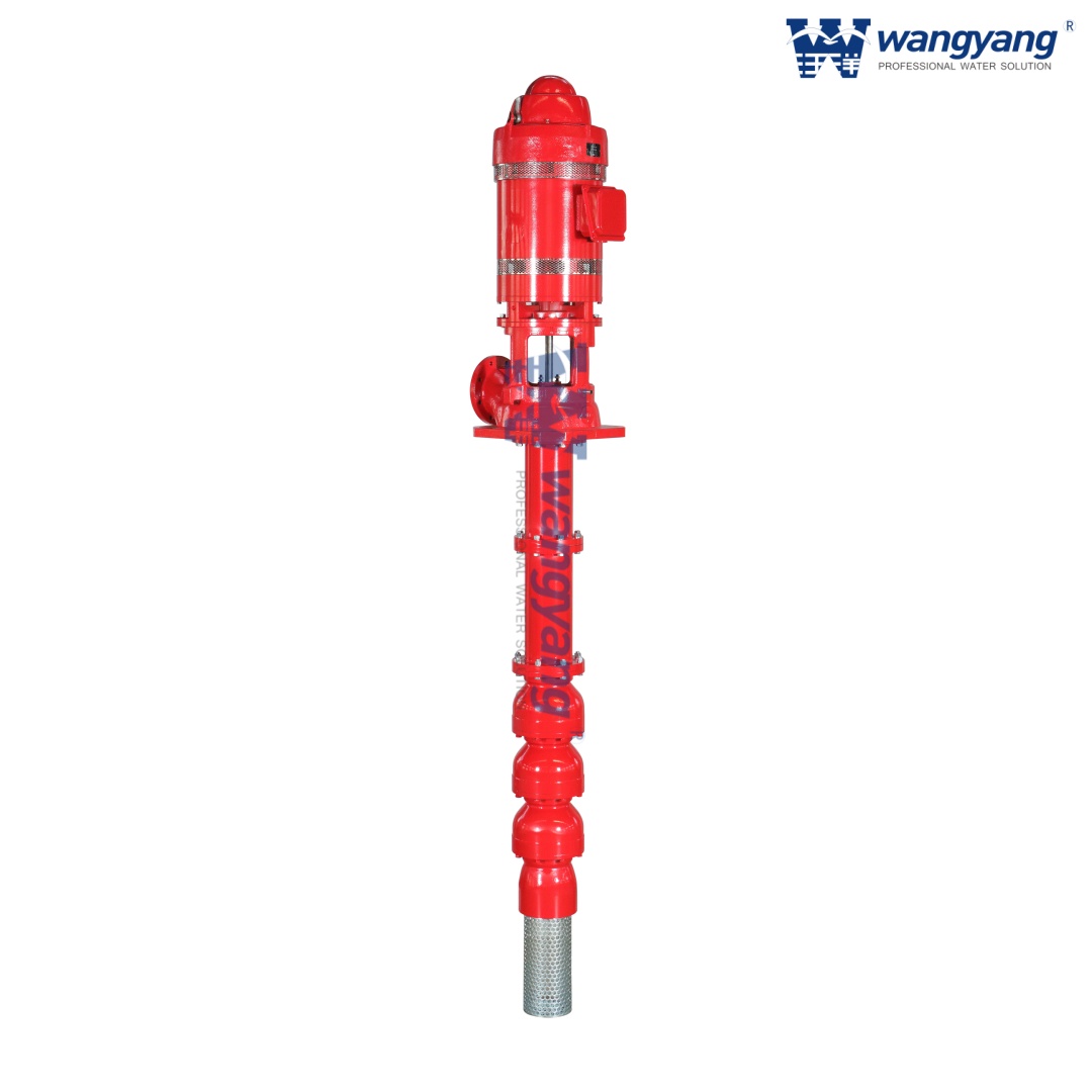
Engineers face specific physical constraints during fire protection design. Standard split-case pumps require a positive suction head to operate correctly. You must supply water to them under pressure or from a flooded suction tank. A Vertical Turbine Fire Pump solves this fundamental problem. It allows systems to draft water directly from below-grade sources. These sources often include wet pits, underground tanks, rivers, and oceans. The vertical design places the pumping elements underwater. This configuration completely eliminates the negative suction constraint forbidden by NFPA 20 standards.
Pump room real estate carries a premium in dense commercial buildings. Horizontal pumps require massive floor spaces for the motor, coupling, and pump casing. Vertical turbines optimize this spatial requirement significantly. You trade vertical clearance for horizontal floor space. The motor mounts directly above the discharge head. This vertical stacking allows you to fit high-capacity systems into surprisingly tight enclosures. Facility managers frequently appreciate this compact footprint during retrofits.
Priming failures represent a significant risk in emergency pumping. Split-case units drawing from low tanks require complex external priming mechanisms. These priming systems often fail during power outages or mechanical faults. Vertical turbines highlight a massive operational advantage here. The bowl assembly remains permanently submerged in the water source. This natural submersion eliminates the need for complex and failure-prone priming systems entirely. The pump stays ready to deliver immediate pressure upon activation.
Certain industries rely almost exclusively on these vertical configurations. You will find them specified heavily across several demanding environments:
Offshore Platforms: They draft raw seawater directly from the ocean to supply deluge systems.
Petrochemical Plants: They draw from massive underground fire water reservoirs securely protected from blast zones.
Large Manufacturing Facilities: They utilize deep wet pits supplied by municipal lines or natural lakes.
Municipal Water Systems: They boost pressure from deeply buried holding tanks into the main distribution grid.
Selecting the right driver dictates overall system reliability. You must choose based on site infrastructure and backup power availability. Both primary options offer distinct advantages and operational risks.
A Vertical Turbine Fire Pump Driven by VHS Motor represents a highly efficient electric solution. The Vertical Hollow Shaft (VHS) motor mounts directly onto the pump discharge head. The pump shaft passes through the hollow motor shaft. They connect at the top via an adjusting nut.
Pros: They require less initial capital and demand minimal maintenance. They occupy a much smaller footprint and offer significantly quieter operation than combustion engines.
Cons/Risks: They carry a strict reliance on reliable grid power. You must provide a secondary automated backup generator if the primary grid fails.
Technical Detail: These motors feature a critical non-reverse ratchet mechanism. Water column backflow can spin the impeller backwards when the pump stops. The ratchet prevents this backspin. It protects the motor and shaft couplings from catastrophic mechanical damage.
Some facilities lack robust electrical grids. These sites require mechanical independence. You can drive the vertical shaft using a diesel engine connected through a right-angle gear drive.
Pros: This setup offers total independence from the electrical grid. It provides unmatched reliability during catastrophic scenarios like earthquakes or severe grid blackouts.
Cons/Risks: They carry a much higher maintenance burden. You must perform regular fuel polishing and battery checks. They require a larger footprint. You must also route complex ventilation and exhaust systems safely outside the pump room.
How do you map site infrastructure to the appropriate driver? First, assess your power redundancy. If you have dual independent electrical feeds or a massive site generator, choose the electric VHS motor. If your facility sits in a remote area prone to power loss, you must specify the diesel engine. You must also evaluate physical room constraints. Diesel engines demand extensive airflow for cooling and combustion. If your pump room lacks exterior wall access, an electric driver becomes mandatory.
Successful implementation relies heavily on precise intake engineering. You must design the sump carefully to ensure reliable hydraulic performance. Even the best pump will fail if the intake pit feeds it turbulent water.
Sump design must ensure laminar, even flow directly to the pump suction bell. Water must approach the bell uniformly from all sides. Improper sump dimensions lead to turbulent eddies. These eddies cause uneven loading on the impeller. This unbalanced force creates severe shaft vibration. Consequently, premature bearing failure occurs rapidly. Engineers must follow strict Hydraulic Institute standards to size the pit width, depth, and wall clearances accurately.
Vortices represent a massive threat to system capacity. Surface vortices look like small tornadoes pulling air from the water surface down into the pump. Subsurface vortices form along the floor or walls. Air entrainment severely reduces pump capacity and causes heavy vibration. You must mitigate this risk through proper pit geometry. Engineers frequently specify anti-vortex plates. They attach these metal plates below the suction bell. Sometimes, they cast specific baffling directly into the concrete sump walls to break rotational flow.
You must maintain a minimum water level above the suction bell. We call this the minimum submergence level. Net Positive Suction Head Available (NPSH-A) must strictly exceed the pump's Net Positive Suction Head Required (NPSH-R). This calculation prevents damaging cavitation. Cavitation occurs when water boils at low pressure, destroying metal impellers. NFPA 20 mandates a strict requirement here. The sump must hold enough water to ensure the pump operates safely at 150% of its rated capacity without cavitating.
Raw water sources carry debris. Lakes, rivers, and oceans contain organic matter and trash. You must install robust suction strainers to prevent debris ingestion. Debris can instantly lock a rapidly spinning impeller. However, you must size these screens carefully. Screens create friction. If the screen mesh is too tight, it causes excessive pressure drops. This drop reduces NPSH-A and starves the pump. Routine screen cleaning protocols remain vital for system readiness.
Proper evaluation requires analyzing multiple technical dimensions simultaneously. You must align hydraulic capabilities with site-specific water conditions and physical piping needs.
You size these systems based on strict performance curves. NFPA 20 dictates performance at three specific intervals. First, you evaluate the rated flow (GPM) and rated pressure (PSI) at 100% capacity. Second, the pump must not exceed 140% of rated pressure at churn (zero flow). Finally, the pump must deliver at least 65% of its rated pressure when operating at 150% of its rated flow capacity. You must map these points precisely to guarantee adequate fire suppression delivery.
Water chemistry dictates your material choices. Ignoring water quality leads to rapid galvanic corrosion and structural failure.
Metallurgy Options for Different Water Sources
Water Condition | Bowl Material | Impeller Material | Application Notes |
|---|---|---|---|
Standard Municipal Potable Water | Cast Iron | Bronze | Ideal for clean, non-corrosive underground tanks. |
Brackish Water / Light Industrial | 316 Stainless Steel | 316 Stainless Steel | Resists mild pitting and moderate chemical exposure. |
Harsh Raw Seawater | Duplex Stainless | Duplex Stainless | Provides superior resistance against high chlorides. |
High-Sand Content Rivers | Ni-Al-Bronze | Ni-Al-Bronze | Offers excellent wear resistance against abrasive sand. |
The column pipe connects the submerged bowls to the surface discharge head. It houses the lineshaft and carries the water upward. You must balance friction loss against cost and weight. Smaller pipes cost less but increase water velocity and friction loss. This loss reduces the final discharge pressure. You must also choose between flanged and threaded column pipes. Threaded pipes work well for shallow depths. Flanged pipes offer easier maintenance access and structural rigidity for deep installations.
You must evaluate lineshaft lubrication methods based on water purity. Open lineshaft construction uses the pumped water to lubricate the shaft bearings. This method works perfectly for clean, filtered water sources. Enclosed lineshaft construction surrounds the shaft in a separate tube. It drips oil or clean water down the tube to lubricate the bearings. You must specify enclosed shafts if you pump abrasive river water. However, strict environmental regulations often prohibit oil-lubricated enclosed shafts near sensitive marine ecosystems.
Installing these systems introduces unique engineering challenges. You cannot simply drop the unit into a hole and expect flawless operation. Rigorous quality control remains mandatory.
Vertical shafts display extreme sensitivity to misalignment. A shaft can stretch 50 feet down into a sump. If the surface foundation is uneven, the entire assembly hangs crookedly. Crooked installations lead directly to severe vibration. This vibration causes rapid shaft wear and premature bearing failure. Installers must use precision machining and plumb lines. They must ensure the discharge head mounts perfectly level on the concrete soleplate.
NFPA 20 requires rigorous annual flow testing. You must prove the pump can still hit 150% of its rated capacity. Designing appropriate testing infrastructure upfront saves immense trouble later. You must pipe a dedicated test header back to the source or to a safe drainage area. Alternatively, you can install specialized inline flow meters. These meters allow you to safely route high-velocity water back into the sump without flooding the property.
Facility managers must acknowledge modern supply chain realities. Manufacturers build standard horizontal pumps in high volumes. They sit on warehouse shelves ready for shipping. Conversely, vertical turbine configurations are heavily engineered-to-order. Manufacturers must custom-cut the column pipe lengths, size the bowl assemblies, and machine the lineshafts to match your exact pit depth. You must factor these extended manufacturing lead times into your construction schedule early.
Regulatory compliance remains non-negotiable in fire protection. You cannot use standard agricultural or municipal vertical pumps for fire duty. Every single major component must be specifically listed and approved for fire protection service. This requirement covers the pump bowl assembly, the driver, the controller, and the right-angle gear drive. You must verify that the system carries Underwriters Laboratories (UL) Listing and Factory Mutual (FM) Approval. Substituting non-listed parts voids your facility's insurance coverage instantly.
Choosing a vertical turbine setup requires balancing water source depth, power infrastructure, and metallurgy. You cannot ignore sump design or driver redundancy without risking catastrophic failure during an emergency. Properly specified systems provide decades of reliable safety, but they demand rigorous upfront engineering.
We recommend taking immediate action to solidify your design. First, compile your required flow and head parameters based on your fire sprinkler hazard analysis. Second, conduct a comprehensive water quality analysis if you plan to draft raw water from a lake or ocean. Finally, consult directly with an MEP engineer or a certified pump manufacturer. They will help you begin preliminary sump design and navigate the complex UL/FM listing requirements.
A: Vertical in-line pumps act as booster pumps. They sit within the piping network and require positive pressure from a municipal supply to function. Conversely, vertical turbines feature submerged bowls. They draft water vertically from below-grade sources operating under negative suction pressure.
A: No, they cannot run dry. Dry running destroys the internal water-lubricated bearings and melts the mechanical seals within seconds. NFPA 20 strictly mandates minimum submergence levels to guarantee the pump always has adequate water coverage before and during operation.
A: Depth is theoretically limited only by lineshaft length and motor horsepower capabilities. While municipal deep-well variants can reach hundreds of feet, typical commercial fire protection applications range from 10 to 50 feet deep to draft from standard underground reservoirs.
A: You must routinely lubricate the motor thrust bearings. You must also inspect the non-reverse ratchet mechanism to ensure it freely engages. Finally, you must verify the packing gland drip rates at the discharge head to ensure the top shaft bearing receives proper cooling.

