

Views: 0 Author: Site Editor Publish Time: 2026-07-30 Origin: Site


Extracting water from below-grade sources presents severe hydraulic limitations for fire protection systems. Engineers face unique challenges when water sits in deep wells, underground reservoirs, or concrete sumps. Standard centrifugal pumps cannot safely extract this water. They rely on positive suction pressure to operate correctly. Without it, they fail.
You need a reliable, code-compliant solution. A Vertical Turbine Fire Pump is the only configuration formally recognized by NFPA 20 for operating under negative suction head conditions without external priming systems. It solves the underlying physics problem by submerging the pumping mechanism directly into the water source.
The stakes remain incredibly high. Improper design or poor specification leads directly to cavitation. This causes severe mechanical degradation. Worse, non-compliant designs result in catastrophic system failure during critical fire events. This guide outlines vital design requirements, drive selection criteria, and strict NFPA 20 compliance rules. You will learn how to evaluate and specify the exact vertical turbine system your facility needs.
Compliance Priority: NFPA 20 strictly prohibits the use of end-suction or split-case pumps where negative suction head exists; submerged impellers are mandatory.
Drive Flexibility: Both electric and diesel configurations are viable, but require specific structural considerations (e.g., right-angle gear drives for diesel).
System Integration: Pre-engineered skid-mounted packages and correctly sized jockey pumps significantly reduce onsite alignment errors and installation friction.
Critical Risk Factor: Accurate calculation of minimum submergence and static water draw-down is the primary defense against vortexing and cavitation.
Standard fire pumps fail when water sources sit below the pump centerline. Horizontal split-case and end-suction pumps rely heavily on positive inlet pressure. When they pull water upwards, they create a vacuum inside the suction piping. This causes a dangerous drop in vapor pressure.
Water boils rapidly at ambient temperatures when pressure drops too low. This phenomenon generates thousands of tiny vapor bubbles. As these bubbles hit the high-pressure zones of the impeller, they collapse violently. We call this cavitation. It destroys metal components in minutes. Standard pumps also require unreliable priming systems to push air out of the pipes. NFPA 20 strictly rejects this reliance on priming for critical life-safety systems.
Vertical turbine systems eliminate Net Positive Suction Head Available (NPSHa) issues completely. They achieve this by keeping the pump bowls and impellers permanently submerged underwater. The pump pushes water up the column pipe rather than pulling it.
Best Practice: Always position the bowl assembly deep enough to ensure constant submergence, even during dry seasons. Because the impellers remain underwater, they never require priming. The system stands constantly ready to deliver maximum flow the moment a fire controller demands it.
Mechanical rooms carry high construction costs. Horizontal pump arrangements consume massive amounts of floor space. They require sprawling suction headers and long pipe runs.
Vertical orientation offers a massive architectural benefit. By stacking the motor vertically over the discharge head, you drastically reduce the mechanical room footprint. You utilize vertical real estate instead. This allows facility managers to design smaller, more efficient pump houses above deep underground tanks.
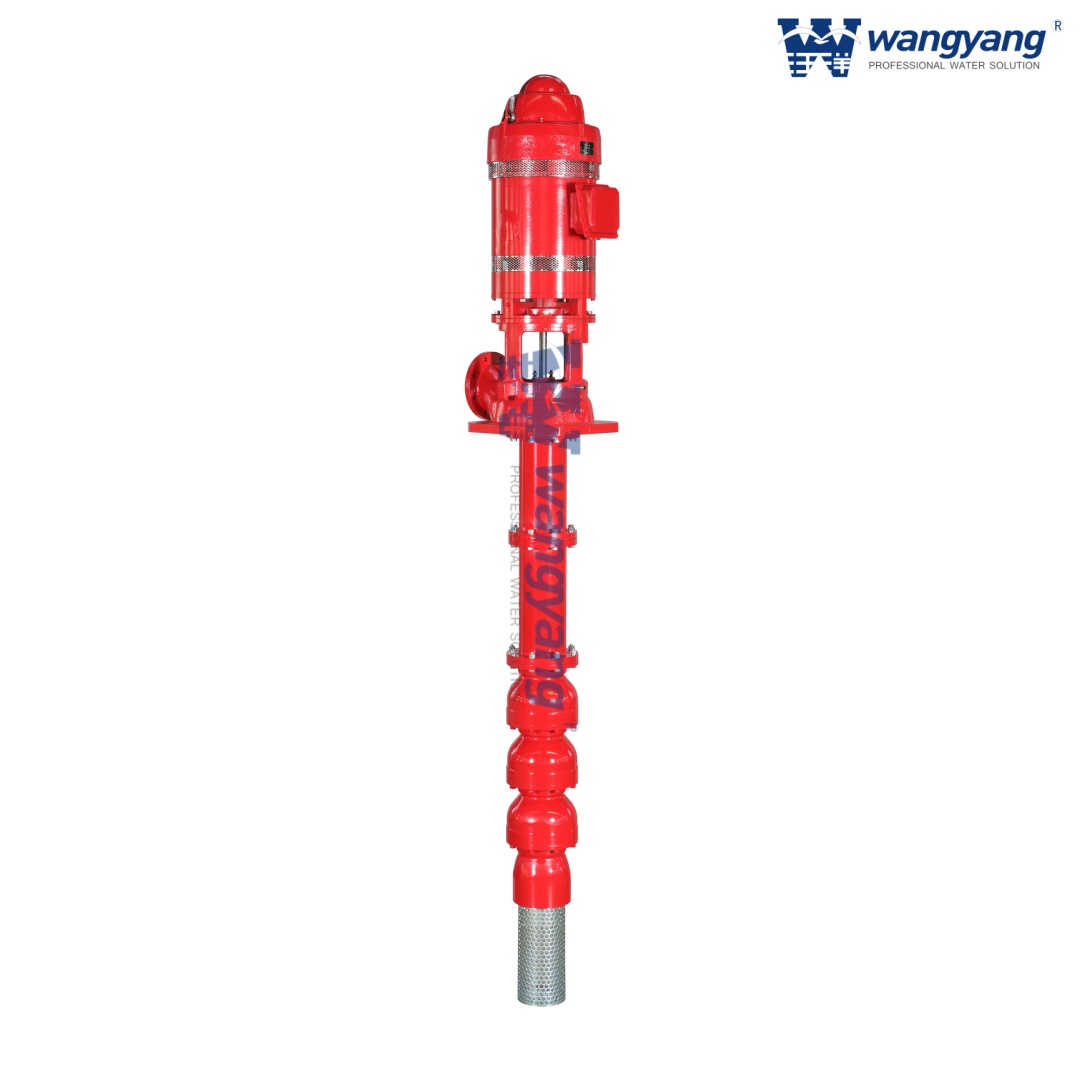
NFPA 20 outlines uncompromising rules for pump depth. The code requires the second impeller from the bottom of the bowl assembly to remain fully submerged at all times. You must measure this at the absolute lowest pumping water level.
Common Mistake: Many engineers size the column pipe based only on the static water level. They forget to calculate maximum drawdown. During mandatory 150% capacity flow tests, the water level in a well or tank drops significantly. You must calculate this dynamic drop accurately. If the water level falls below that second impeller during a high-flow event, the pump will ingest air and fail.
Below-grade pits collect debris. NFPA 20 mandates the installation of specific basket strainers on the suction bell. These strainers prevent large debris from entering and shattering the impellers. The code dictates precise free-area ratios for the mesh to ensure adequate water flow.
You must also maintain strict clearance distances between the bottom of the suction bell and the pit floor. If you place the bell too close to the floor, you restrict flow and starve the pump. If you place it too far away, or fail to provide adequate side clearances, you invite vortexing. Vortexing creates swirling whirlpools that drag surface air directly into the pump intake.
The column pipe connects the underwater bowls to the surface discharge head. It serves as both the water conduit and the structural support for the internal shaft. You must address friction loss calculations carefully as water travels up this pipe. Deep wells introduce significant friction penalties.
Engineers must choose between flanged or threaded column connections. Threaded connections work well for shallow, low-pressure applications. However, deep-well systems operating under immense pressure parameters require heavy-duty flanged connections. Flanges handle the dynamic torque of the motor starting much better than threads.
Mechanically, these systems remain straightforward. They utilize Vertical Hollow Shaft (VHS) motors mounted directly on the discharge head. The hollow shaft allows the pump shaft to pass through the top, making precise impeller adjustments simple. A non-reverse ratchet mechanism prevents the water column from spinning the pump backward when the motor shuts off.
An electric vertical turbine fire pump works best for facilities featuring highly reliable primary and secondary power grids. They are ideal for urban hospitals or industrial plants with massive backup generator arrays.
The primary advantages include much lower maintenance overhead and exceptionally quiet operation. They vibrate less and require no fuel storage. However, their major drawback remains their absolute dependence on electrical infrastructure stability.
Diesel systems introduce complex mechanical components. A diesel engine outputs power horizontally. You must convert this horizontal rotation into vertical rotation to spin the pump shaft. This requires a heavy-duty right-angle gear drive. Universal joints and flexible drive shafts connect the engine to the gear drive.
A diesel vertical turbine fire pump excels in remote locations or deep-well applications. They are mandatory where local grid reliability cannot meet strict NFPA 20 secondary power requirements.
They provide complete grid independence. They will run as long as fuel remains in the tank. However, this independence demands a larger spatial footprint. You must accommodate bulk fuel tanks, exhaust routing, and engine cooling loops. Furthermore, managing torsional vibration between the engine, gear drive, and pump shaft becomes a critical engineering task.
Table: Drive Configuration Comparison
Feature | Electric (VHS Motor) | Diesel (Right-Angle Gear) |
|---|---|---|
Grid Dependence | High (Requires robust primary/secondary power) | None (Completely independent operation) |
Maintenance Overhead | Low (Basic greasing, electrical checks) | High (Oil, fuel polishing, battery maintenance) |
Spatial Footprint | Minimal (Vertical stack only) | Large (Requires fuel tanks, exhaust, batteries) |
Vibration Profile | Smooth, predictable dynamic loads | High torsional vibration, requires robust foundation |
You must never rely on your primary turbine pump to maintain everyday system pressure. Underground piping networks always experience minor pressure drops. Small leaks, temperature fluctuations, and weeping valves deplete line pressure slowly.
You must pair the main turbine with an in-line jockey pump. The jockey pump senses these minor drops and activates to repressurize the system. By absorbing these small fluctuations, the jockey pump prevents the primary turbine from short-cycling. Short-cycling occurs when a massive motor turns on and off rapidly. This violent action degrades the motor windings, twists the internal shaft, and drastically shortens system life.
Modern engineers face a choice between onsite component-builds and factory-packaged solutions. Pre-engineered packages dominate modern pump house design. We evaluate these packaged solutions using specific criteria:
Factory Alignment: The manufacturer aligns the driver, gear drive, and discharge head using laser precision in a controlled environment.
Integrated Piping: Engineers pre-pipe the test header, flow meter, and relief valves to exact NFPA specifications.
Unified Wiring: Controllers, sensors, and power conduits arrive pre-wired, eliminating dangerous onsite electrical errors.
The business value remains undeniable. A pre-wired, pre-piped, and pre-aligned skid system accelerates mechanical room build-outs. It drastically reduces onsite contractor friction. Most importantly, buying a packaged vertical turbine fire pump ensures the total assembly holds UL Listing and FM Approval. You avoid the compliance nightmares of mixing and matching uncertified components.
Shaft misalignment represents the most common failure point in vertical installations. Many contractors falsely assume factory alignment survives heavy highway transit. It never does. You must re-verify and adjust the alignment between the motor, gear drive, and the column shaft onsite.
Using precision dial indicators is mandatory. Even a few thousandths of an inch of runout creates severe vibration. This misalignment transfers immense stress to the lineshaft bearings. Premature bearing failure follows shortly, leading to a catastrophic shaft snap during operation.
Vertical pumps generate intense dynamic loads. They transfer the entire weight of the suspended water column directly onto the foundation. You must design a rigid, mass-heavy concrete pad to absorb these forces.
This becomes especially critical in diesel configurations. Diesel engines produce severe torsional forces that twist the entire base. Contractors must use high-strength, non-shrink epoxy grout beneath the discharge head and engine base plates. Standard cement grout will crack and crumble under the violent vibration of a weekly diesel pump test.
Commissioning exposes the harsh realities of onsite testing. NFPA 20 requires rigorous acceptance tests before signing off on the building. The system must prove it can deliver 150% of its rated capacity.
During this maximum flow test, inspectors monitor two vital metrics. First, the water level must not break the minimum submergence threshold. Second, the system must not draw a vortex. If the pit lacks sufficient depth, or if the contractor failed to install an anti-vortex plate, swirling funnels of air will reach the suction bell. The test fails immediately if vortexing occurs.
Never engage a pump manufacturer without concrete hydrological data. MEP engineers must gather specific inputs to ensure accurate hydraulic sizing. Missing data guarantees a rejected submittal. You need:
Accurate static water levels.
Calculated pumping water levels (incorporating expected drawdown).
Total dynamic head requirements to reach the highest sprinkler.
Precise GPM and PSI requirements per the hydraulic fire model.
Exact physical dimensions of the underground pit or well casing.
Not all manufacturers deliver the same level of engineering support. Evaluate potential vendors through these critical lenses:
Do they perform in-house hydraulic performance testing across the full curve prior to shipping?
Are both the pump bowls and the specific drive configuration UL Listed and FM Approved as a complete assembly?
Can their engineering team provide a documented torsional vibration analysis for diesel-driven right-angle gear setups?
We recommend engaging a qualified manufacturer extremely early in the schematic design phase. Finalize your well diameters, pit depths, and suction clearances long before contractors pour any concrete. Retrofitting a shallow concrete pit to meet NFPA submergence rules costs a fortune and delays occupancy permits.
Selecting a vertical turbine fire pump represents a high-stakes engineering decision. The physical realities of below-grade water sources eliminate standard centrifugal pumps from the conversation. You must rely on vertical, submerged technology to guarantee water delivery during a crisis.
Success requires carefully balancing NFPA 20 Chapter 7 requirements with the appropriate drive mechanism. Whether you choose a VHS electric motor or a diesel-driven right-angle gear, precision alignment and accurate drawdown calculations remain non-negotiable. Mastering these elements ensures a highly resilient, inspection-ready fire protection system.
Do not leave these complex hydraulic calculations to chance. Consult with dedicated fire pump application engineers today. Request a comprehensive technical sizing review for your specific underground reservoir project before finalizing your mechanical blueprints.
A: No. Standard submersible pumps are rarely UL/FM approved for dedicated fire protection systems. NFPA 20 dictates vertical turbine pumps for below-grade negative suction applications to ensure reliability, standardized testing, and accessible motor maintenance.
A: Both use dedicated, UL/FM-approved fire pump controllers. However, the diesel controller manages dual-battery starting sequences, engine instrumentation, and cooling loop monitoring. The electric controller focuses on managing massive inrush currents using soft start or wye-delta configurations, alongside phase monitoring.
A: While technically capable of drawing from several hundred feet (common in deep-well industrial applications), the practical depth for fire systems is limited. The engineering required for the column pipe, shaft elongation, and the driver's ability to overcome extreme static lift dictates these practical limits.
A: Vortexing is prevented by strictly adhering to the NFPA 20 minimum submergence depths. You must also ensure the suction bell is sized perfectly to maintain low inlet velocities. If clearance remains exceptionally tight, installing a certified anti-vortex plate is mandatory.

